like a transformer we do step up operations for boosting young talents and we perform step down operation for removing self doubt, negativity and lazyness...boom! we just revealed one of our top secret
Learning course is different and working on real time projects is different, you might herd it so many times but you will not believe that statement anymore when you join us. why? well we can’t reveal all our secrets right here.
Get Course Information 24*7
EMCO MEP Center Provides Best Electrical CAD Courses in Gulbarga

ELECTRICAL & ELV DESIGNING
Electrical and ELV (Extra Low Voltage) designing is the process of designing electrical and low voltage systems for buildings. Electrical systems include power distribution, lighting, and communication systems, while ELV systems include security.

ELECTRICAL AUTO CAD DRAFTING
Electrical AutoCAD drafting is a process of creating detailed 2D technical drawings of electrical systems using the AutoCAD software tool. AutoCAD is widely used in the electrical engineering industry for designing, drafting, and documentation of electrical systems.
ELECTRICAL BIM REVIT
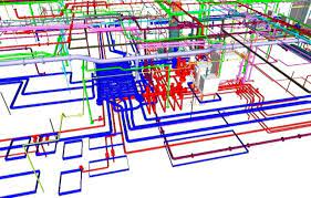
Electrical BIM (Building Information Modeling) in Revit is a process that involves creating a virtual 3D model of an electrical system within a building. It allows electrical engineers and designers to collaborate in a digital environment to plan and design.
BEST ELECTRICAL AND ELV COURSE IN GULBARGA
MODULE 1 - INTRODUCTION
If you are interested in learning more about electrical and ELV (Extra Low Voltage) design, there are a variety of courses available that can help you develop your skills and knowledge in this area. Here are some options:
Online Courses: There are many online courses available that cover electrical and ELV design. Some of these courses are self-paced, allowing you to learn at your own speed, while others are instructor-led and follow a set schedule. You can find courses on platforms such as Udemy, Coursera, and edX.
Technical Institutes: Many technical institutes offer courses and programs in electrical and ELV design. These programs may be available on a full-time or part-time basis and can provide you with hands-on experience in designing and implementing electrical and ELV systems. Examples include the National Institute of Electronics & Information Technology (NIELIT) and the National Skill Development Corporation (NSDC) in India.
Certification Programs: Various organizations offer certification programs in electrical and ELV design. These programs can provide you with formal recognition of your skills and knowledge in this area, which can be helpful when seeking employment. Examples include the Certified Electrical Designer (CED) and the Registered Communications Distribution Designer (RCDD) programs.
Industry Associations: Industry associations such as the Institute of Electrical and Electronics Engineers (IEEE) and the National Fire Protection Association (NFPA) offer courses and training in electrical and ELV design. These organizations can also provide you with access to industry events and networking opportunities.
Overall, there are many options available for learning about electrical and ELV design. Consider your goals and learning preferences when selecting a course or program, and be sure to research the reputation and quality of the provider before enrolling.
- Introduction Of Current, Voltage, Power, circuit etc.
- Project execution
- Units Concept
- Classification Of Building Services
- Electrical Accessories
- Internal Wiring and Electrical Distribution System
MODULE 2 — LUX OR FC CALCULATIONS
LUX and FC are both units of measurement for illuminance, which is the amount of light that falls on a surface per unit area. LUX is the metric unit of illuminance, while FC (foot-candles) is the imperial unit of illuminance.
The calculation of illuminance in LUX or FC involves the following steps:
Determine the light source: The first step is to determine the light source and the distance between the light source and the surface being illuminated.
Determine the luminous flux: The luminous flux is the amount of light emitted by the light source and is measured in lumens. The luminous flux is usually provided by the light manufacturer or can be measured using a light meter.
Determine the angle of incidence: The angle of incidence is the angle at which the light hits the surface being illuminated. This is important as the illuminance will vary depending on the angle of incidence.
Calculate the illuminance: The illuminance is calculated by dividing the luminous flux by the surface area being illuminated and the angle of incidence.
For example, to calculate the illuminance in LUX, the formula is:
Illuminance (LUX) = Luminous flux (lm) / Surface area (m²) x Angle of incidence (°)
To calculate the illuminance in FC, the formula is:
Illuminance (FC) = Luminous flux (lm) / Surface area (ft²) x Angle of incidence (°)
Overall, calculating illuminance in LUX or FC is an important step in designing lighting systems and ensuring that adequate lighting levels are achieved for various applications, such as residential, commercial, and industrial settings.
- Measuring Light Levels the Four Lighting Metrics
- Lumen Method of Light Calculation
MODULE 3 — CL AND MD LOAD CALCULATIONS
CL and MD load calculations are important in electrical engineering to determine the total electrical load of a building or facility.
CL (Connected Load) is the sum of the power rating of all connected electrical devices in a building or facility. This includes lighting fixtures, electrical appliances, and other electrical equipment. The CL is usually calculated in kilowatts (kW) or in kilovolt-amperes (kVA).
MD (Maximum Demand) is the maximum power demand that a building or facility can require at any given time. This is determined by the simultaneous use of all electrical devices at their maximum rating. The MD is usually calculated in kilowatts (kW) or in kilovolt-amperes (kVA).
The calculation of CL and MD load involves the following steps:
Identify all electrical devices: The first step is to identify all electrical devices in the building or facility that require power.
Determine the power rating: The power rating of each electrical device is determined in kilowatts (kW) or in kilovolt-amperes (kVA). This information is usually provided by the manufacturer’s specifications.
Calculate the CL: The CL is calculated by adding up the power rating of all connected electrical devices in the building or facility. The CL is usually calculated in kilowatts (kW) or in kilovolt-amperes (kVA).
Calculate the MD: The MD is determined by considering the maximum demand that the electrical devices will place on the electrical system at any given time. This is calculated by using a diversity factor, which accounts for the fact that not all devices will be in use at the same time. The MD is usually calculated in kilowatts (kW) or in kilovolt-amperes (kVA).
Overall, CL and MD load calculations are important in determining the electrical requirements of a building or facility. These calculations help ensure that the electrical system is properly designed to handle the expected load and can prevent issues such as power outages and electrical system failures.
- Estimation of Load Requirements
- Special Features Applicable for High-Rise Apartment Building
- Feeding system High voltage distribution network
MODULE 4 — TRANSFORMER SECTIONS AND POWER FACTOR CORRECTIONS
Transformers are electrical devices that are used to transfer electrical energy between two or more circuits through electromagnetic induction. Transformer sections are used to divide large transformers into smaller sections to improve their efficiency and reduce their size. Transformer sections are typically used in high-voltage electrical systems, such as power transmission and distribution systems.
Power factor correction is the process of improving the power factor of an electrical system. The power factor is the ratio of the real power (in kilowatts) to the apparent power (in kilovolt-amperes) of an electrical system. A low power factor can cause problems such as increased energy costs, reduced system efficiency, and equipment failure. Power factor correction involves adding capacitors or inductors to the electrical system to improve its power factor.
The topics covered in Module 4 may include:
Transformer sections: The principles of transformer operation, transformer design, transformer sectioning techniques, and transformer section connections.
Power factor correction: The causes of low power factor, the advantages of power factor correction, the different types of power factor correction methods, and the selection of power factor correction equipment.
Power factor measurement and analysis: The measurement of power factor, the calculation of power factor correction, the analysis of power factor data, and the interpretation of power factor results.
Harmonic distortion: The effects of harmonic distortion on power factor, the measurement of harmonic distortion, and the reduction of harmonic distortion.
Overall, Module 4 is an important part of electrical engineering as it covers topics related to improving the efficiency and reliability of electrical systems, which are important considerations for many industries and applications.
- Transformers
- Selection of transformers and protection
- Power factor correction
- Power Distribution System
- Earthing systems
- Substation Load Estimation
MODULE 5 — FAULT LEVEL, BREAKERS CABLE AND VOLTAGE DROP CALCULATIONS
Fault level calculations are used to determine the level of electrical fault current that can occur in an electrical system. Fault currents can cause damage to equipment, create safety hazards, and cause power outages. Breakers are electrical devices that are used to protect electrical systems from overcurrents, including fault currents. Cables are used to transmit electrical power between devices or systems. Voltage drop calculations are used to determine the amount of voltage drop that occurs in a cable or electrical system as a result of the resistance of the cable or system.
The topics covered in Module 5 may include:
Fault level calculations: The principles of fault current, the calculation of fault current, the analysis of fault current data, and the interpretation of fault current results.
Breakers: The types of breakers, the principles of breaker operation, the selection of breakers, and the installation and maintenance of breakers.
Cables: The types of cables, the principles of cable operation, the selection of cables, and the installation and maintenance of cables.
Voltage drop calculations: The principles of voltage drop, the calculation of voltage drop, the analysis of voltage drop data, and the interpretation of voltage drop results.
Protection coordination: The principles of protection coordination, the analysis of protection coordination data, and the interpretation of protection coordination results.
Overall, Module 5 is an important part of electrical engineering as it covers topics related to the protection and performance of electrical systems. These calculations and considerations are important in ensuring that electrical systems operate safely and efficiently.
- How to Calculate Fault Current for Electrical System
- Calculate Size of Main ELCB & Brach MCB of Distribution Box
- Introduction of Cable
- Calculate Cable Size
MODULE 6 — CONTAINMENT OR TRAY SIZE SELECTION
Containment or tray size selection involves the selection of cable trays or conduit systems for the installation of electrical cables. Cable trays and conduit systems are used to support and protect cables, and they are commonly used in commercial, industrial, and residential electrical installations. The size of the cable tray or conduit system is determined by the size and number of cables that will be installed.
The topics covered in Module 6 may include:
Cable tray and conduit systems: The types of cable trays and conduit systems, the advantages and disadvantages of each type, and the selection of cable trays and conduit systems.
Cable sizing: The principles of cable sizing, the calculation of cable sizes, the analysis of cable sizing data, and the interpretation of cable sizing results.
Containment sizing: The principles of containment sizing, the calculation of containment sizes, the analysis of containment sizing data, and the interpretation of containment sizing results.
Cable routing: The principles of cable routing, the selection of cable routing methods, and the installation of cable routing systems.
Overall, Module 6 is an important part of electrical engineering as it covers topics related to the selection and installation of cable trays and conduit systems. The correct selection and installation of these systems are important in ensuring the safety, reliability, and performance of electrical systems.
- Types of Trays or Containment
- Calculate Size of Cable Tray& Trunking
- Tables & Charts for Proper Cable & Wire Sizes
MODULE 7 — ELV
ELV systems are electrical systems that operate at voltage levels below 50 volts AC or 120 volts DC. ELV systems are commonly used in telecommunications, security, and data communications systems. These systems require specialized engineering knowledge and expertise to design and install.
The topics covered in Module 7 may include:
ELV system design: The principles of ELV system design, the selection of ELV system components, and the integration of ELV systems with other electrical systems.
ELV system installation: The installation of ELV system components, the testing of ELV systems, and the commissioning of ELV systems.
ELV system maintenance: The maintenance of ELV system components, the troubleshooting of ELV systems, and the repair of ELV systems.
ELV system safety: The principles of ELV system safety, the identification of ELV system hazards, and the implementation of ELV system safety measures.
Overall, Module 7 is an important part of electrical engineering as it covers topics related to the design, installation, maintenance, and safety of ELV systems. These systems play a critical role in modern telecommunications, security, and data communications systems, and it is important to have a thorough understanding of their design, installation, and operation.
- TELEPHONE AND DATA SERVICE
- CCTV
- ACCESS CONTROL
- FIRE ALARM
- PUBLIC ADDRESS
- MATV
Why Choose Emco MEP Training Center
100% Placement Assurance
One to One Teaching
Experienced Lecture
FAQ
AutoCAD is a computer-aided design (CAD) software application developed by Autodesk that allows users to create 2D and 3D designs and models. It is used in a variety of industries, including architecture, engineering, construction, and manufacturing.
AutoCAD offers a range of tools and features that enable users to create precise and detailed designs, including drawing and editing tools, dimensioning tools, and annotation tools. It also allows users to work with a wide range of file formats, making it easy to collaborate with others and share designs.
AutoCAD is widely used in the design and construction industry for tasks such as creating architectural plans, engineering drawings, and building models. It is also used in the manufacturing industry for tasks such as creating product prototypes and designing production processes.
AutoCAD is available in different versions, including AutoCAD LT, which is a simplified version with fewer features, and AutoCAD Architecture, which is specifically designed for architectural drafting and design.
AutoCAD is used by professionals in a wide range of industries, including:
Architecture: Architects use AutoCAD to create building plans, elevations, and sections.
Engineering: Engineers use AutoCAD to create detailed designs of mechanical, electrical, and plumbing systems, as well as structural components and civil infrastructure.
Construction: Contractors use AutoCAD to generate construction plans, including site plans, floor plans, and construction details.
Manufacturing: Manufacturers use AutoCAD to create product designs and models, including prototypes and production designs.
Interior Design: Interior designers use AutoCAD to create designs for interior spaces, including floor plans and 3D models.
Landscaping: Landscape designers use AutoCAD to create designs for outdoor spaces, including parks, gardens, and public spaces.
Film and Entertainment: Designers in the film and entertainment industry use AutoCAD to create visual effects, sets, and scenery.
Overall, AutoCAD is used by professionals who require precise and detailed designs and models in their work, regardless of the industry they work in.
There are several benefits of using AutoCAD for designing and drafting. Some of these benefits include:
Increased productivity: AutoCAD provides a range of tools and features that allow designers to create and edit designs quickly and easily, reducing the time and effort required to complete a project.
Accuracy and precision: AutoCAD provides precise and accurate tools that ensure the accuracy of designs, reducing errors and ensuring that designs are completed to a high level of precision.
Consistency and standardization: AutoCAD allows designers to create and save templates and standard details, ensuring consistency and standardization in designs and reducing the need for repetitive work.
Improved communication: AutoCAD allows designers to create detailed and clear drawings and models that can be easily shared with team members and stakeholders, improving communication and collaboration.
Efficient revisions: AutoCAD allows designers to make revisions and changes quickly and easily, without the need to redraw the entire design.
Compatibility and interoperability: AutoCAD is compatible with a wide range of file formats, making it easy to share designs and collaborate with others using different software applications.
Cost savings: AutoCAD can help to reduce project costs by improving productivity, reducing errors, and increasing efficiency.
Overall, the benefits of using AutoCAD make it an essential tool for professionals in a wide range of industries, from architecture and engineering to manufacturing and construction.